Automotive And Commercial Locksmith

6105 Johnson Street, Hollywood FL, 33024
(954)347-9566 verified

Blog

G.M. Passlock 1

5/2/2012 10:36:00 PM by Automotive And Commercial Locksmith

Introduced by General Motors on the 1995 Chevy Cavalier Z-24, the Passlock 1 ignition lock is also found on the Pontiac Grand Am, Oldsmobile Achieva, and Buick Skylar (GM's N Cars) and the Cavalier and Pontiac Sunfire (J cars), beginning with the 1996 model year.

Passlock 1 uses a double-sided, 10 cut key in a single key system. Passlock 1, designed and produced by Strattec, features a small magnet in a side bar cylinder. A Hall effect sensor is mounted on the case assembly. When the cylinder rotates, the magnet registers on the sensor's three points. The sensor electronically signals the vehicle's onboard computer, and the car is allowed to start if the electromagnetic value matches the code stored in the computer. A 10 minute wait (after three unsuccessful start attempts) is programmed into the system as a theft deterrent. Any attempt to force rotate the cylinder will damage the magnet and  immobilize the vehicle.

Each Passlock 1 ignition operates on one of 10 possible electromagnetic values. Adding to the security of the system, there is no way to visually identify which one of the 10 values the lock contains. Replacement locks are sold randomly. Lock repairs require a quick and easy reprogramming of the vehicle computer to match the value of the newly installed Passlock 1.

Reprogramming :

  1. After replacing the lock, try to start the vehicle with the correctly cut key. There is a one in ten chance that the car will start.
  2. If the new lock does not match the electronic value in the vehicle's computer, an indicator light on the instrument panel will begin flashing and the car will be disabled.
  3. Leave ignition in the ON or RUN position.
  4. After approximately 10 minutes, the light will stop flashing and remain on. The onboard computer has been programmed to accept the new lock's signal.
  5. The car can be started.

Locksmith Services (954) 347-9566


Transponder

5/2/2012 10:22:00 PM by Automotive And Commercial Locksmith

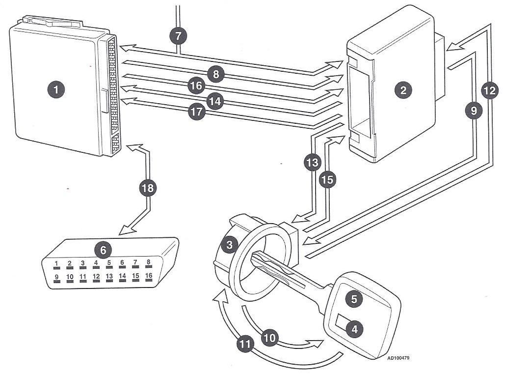
(1) Engine Control Module (E.C.M). 

(2)  Immobilizer Control Module.

(3) Antenna Ring.

(4) Transponder.

(5) Key.

(6)  Data Link Connector (D.L.C).

(7) Ignition On Signal.

(8) Unlock Request.

(9) 100-150 KHZ Carrier Signal.

(10) Get Key Code.

(11) Send Key Code.

(12)  Key Code to Immobilizer Control Module.

(13) Rolling Code Algorithm to Key.

(14) Rolling Code Algorithm to E.C.M.

(15) Rolling Code Calculation from Key.

(16)  Rolling Code Calculation from E.C.M.

(17) Unlock Request Granted.

(18) Diagnostics and Programming

Transponder System

  • The transponder (4) consists of a resonator  and IC circuit includes a processor and non-volatile memory, embedded into the ignition key or remote transmitter
  • A separate power supply is not required as the transponder derives its power from an induced signal, at the correct frequency, emitted by the antenna ring from the immobilizer control module (I.C.M)
  • When the resonator circuit receives a signal at the correct frequency it generates sufficient power to enable the IC circuit and processor to operate and to transmit its identification code.
  • Each transponder ignition key or remote transmitter has a unique code out of millions of combinations.

Antenna Ring

  • The antenna ring is a coiled wire (aerial) located around the ignition lock assembly. It has two functions, the first being to transmit a carrier frequency signal, usually in the 100-150 kHz range, from the immobilizer control module (I.C.M) to the transponder. The second is to transmit the identification code of the transponder back to the immobilizer control module.

Immobilizer Control Module (I.C.M)

  • The immobilizer control module (I.C.M) can be a stand alone component or its function can be integrated into other control modules.
    It communicates with the antenna ring around the ignition switch and the engine control module (E.C.M)
  • When the ignition switch is turned to the ON position, a carrier frequency signal is sent to the antenna ring around the ignition lock assembly. Some systems have the ability to adjust the frequency  of this signal, up or down, to ensure trouble free communication without interference from other signals.

Engine Control Module (E.C.M)

  • The engine control module (E.C.M) needs special software designed for immobilizer system operation. To enhance security and prevent components from being swapped from another vehicle, the immobilizer control module (I.C.M) will only be able to communicate with the E.C.M that it recognizes and is registered with it from new.

System Operation

  • When the ignition is switched on  and an attempt made to start the engine the E.C.M sends an unlock request to the immobilizer control module.
  • The immobilizer control module outputs a 100-150 kHz carrier wave to the antenna ring. The signal is induced into the transponder. The transponder responds to this induced signal by outputting the key code identification witch is transmitted back to the immobilizer control module via the antenna ring.
  • This key code identification is then compared with the stored code in the immobilizer control module memory. At this point the immobilizer control module only recognizes this as one of series of registered keys.
  • To further increase security, the immobilizer control module transmit a random code to the E.C.M and the key transponder and request an algorithmic calculation to be performed. the immobilizer control module also performs this algorithmic calculation independently.

  • The E.C.M  and key transponder return the answers of the algorithmic calculation to the immobilizer control module. A comparison is made and if they match, the unlock request is granted.
  • If any of the calculations do not match the unlock request is denied. the engine will not start or, if already started, will stop.
  • This authentication procedure happens so quickly that the driver may only be aware of a very slight delay between the key being turned and the engine starting.
  • The immobilizer system is automatically reset when the ignition is switched off and the key withdraw from the ignition switch.
  • Many immobilizer systems feature fault memories which can be accessed in various ways by counting immobilizer warning light flashes, bridging data link connector (D.L.C) terminals with a voltmeter or LED tester, or using suitable diagnostic equipment.

Programming

  • This procedure is used on the immobilizer control module to ensure that it recognizes the signal emitted by the transponder .

Locksmith Services (954) 347-9566


How to change the combination on a Kwikset Powerbolt 1000?

5/2/2012 3:28:00 PM by Automotive And Commercial Locksmith

Kwikset Lock, Access Control

RESETTING THE CODE:

Please follow these instructions to reset the code on your Powerbolt 1000 unit.

  1. Remove the inner cover plate from the lock.
  2. Locate the small round program button near the left side of the circuit board (Red or Black).
  3. To program, the latch should be extended out in the lock position.
  • Press the reset button once.
  • Enter you 4 to 8 digit code on the exterior keypad follow by the by the lock button. You will hear a beep.
  • Re enter the same 4 to 8 digit code to confirm, the latch should retract to confirm programming. This signals that your code has been accepted.

To enter  a second code, follow the same procedures as in step 3, but this time press the reset button twice the enter your code.

CHANGING THE PASSWORD CODE:

Please  follow instructions.

  1. Manually put the bolt in extended position.
  2. Press PROGRAM button once.
  3. Enter new 4 to 8 digit code follow by the LOCK button once
  4. Press PROGRAM button twice
  5. Enter the same new code follow by the LOCK button once
  6. Press PROGRAM button three times
  7. Enter the same new code follow by the LOCK button once

This steps will program only the new code you enter for your unit.

Locksmith Services (954) 347-9566


How to Change combination on a S&G (Sargent and Greenleaf) three number combination lock? 6600/6700

5/2/2012 2:53:00 PM by Automotive And Commercial Locksmith

Important: Turn dial slowly and evenly. Do not turn back to regain alignment if you rotate past the number. If an error is made, re dial the entire combination. Count how many times each number is aligned with the index (at the 12 o' clock position); do not count turns. Always view the dial an ring straight on, not at an angle.

TO OPEN:

  • Turn dial left, aligning the first number of your combination with the opening index (12 o' clock) the fourth time it comes to the index.

Curve Left Arrows (Counter clockwise)

  • Turn dial right, aligning second number with the opening index the third time it comes to the index.

Curve Right Arrows (Clockwise)

  • Turn dial left, aligning third number with the opening index the second time it comes to the index.

Curve Left Arrows (Counter clockwise)

  • Turn the dial right until dial comes to a complete stop.

Curve Right Arrow (Clockwise)

To re lock and secure the combination lock, one's close turn the dial to the left at least four revolutions.

CHANGING INSTRUCTIONS:

Important: You must have the correct change key to reset the combination. Do not set the third number of the combination between 5 and 11 on a lock with a dial split at 50. The "forbidden zone" can shift slightly due to installation and tolerances, but will always be between 4 and 12. Do not set adjacent numbers of the combination within five numbers of each other. Do not remove lock cover. If and error is made, re dial the entire combination.

  1. Using the existing combination on the opening index, unlock combination lock, and open safe door. Re lock with safe door open.
  2. Dial the existing combination again, using this time the changing index (at the 11 o' clock position). Keep the third number aligned on the changing index.
  3. Insert change key into key hole on the lock's cover. Change key must be completely inserted.
  4. Rotate key left 90 degrees
  5. Enter a new three number combination using the changing index, dialing as follows:
  • Turn dial left until the first number aligns with the changing index the fourth time.

Curve Left Arrows (Counter clockwise)

  • Turn the dial right until the second new number aligns with the changing index the third time.

Curve Right Arrows (Clockwise)

  • Turn dial left until the third new number aligns with the changing index the second time.

Curve Left Arrows (Counter clockwise)

  • Turn the dial right 10 numbers.

Curve Right Arrow (Clockwise)

  1. Rotate change key right 90 degrees until it stops. Remove change key.
  2. Using the opening index this time, check new combination at least three times before locking the safe.
  3. After changing the opening code, the lock should be opened and locked several times with the safe door open.

Important: Do not select codes such as birthdays or other predictable data which could give a correlation between the user and the opening code.

Locksmith Services (954) 347-9566


Greetings from Automotive And Commercial Locksmith

11/30/2011 10:18:00 PM by Automotive And Commercial Locksmith

We would like to take this opportunity to greet our customers and business associates and proudly announce that we have joined a Local Biz Profiles - Small Business Directory business network.

We are very excited to offer you the latest news and updates, money saving coupons and unbelievable special offers, in addition to detailed business information, user ratings and recommendations.

Sincerely yours,
Automotive And Commercial Locksmith
1227 North State Road 7
Hollywood FL 33021

Copyright © 2006-2024 SHOWMELOCAL Inc. - All Rights Reserved. | Made in NYC
SHOWMELOCAL®.com is Your Yellow Pages and Local Business Directory Network
SHOWMELOCAL® is a registered trademark of ShowMeLocal Inc.


Top